Extrinsic Camera Calibration Using Optimization
Theory

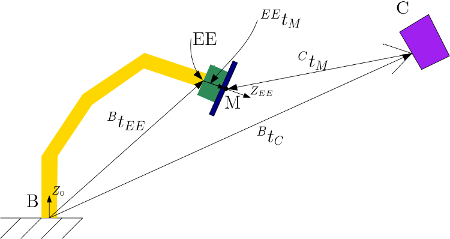
Figure shows the schematic of the robot where B, EE and C represent the base frame (or fixed frame) of the robot, end-effector frame and camera frame respectively. M corresponds to the origin of the marker (april-tags) which is along the Z axis of the EE frame. We know the translation vector, \(^Bt_{EE}\), from the tf topic from the robot. The attachment fitted with the EE is made in SolidWorks and hence the translation,\(^{EE}t_M\) is also known. From the detection algorithm running, we get the translation, \(^Ct_M\). From all these known information, we can write
\begin{equation} ^Bt_{EE} + ^B[R]_{EE} ~^{EE}t_M = ^Bt_C + ^B[R]_C ~^Ct_M \end{equation}
where \(^B[R]_{EE}\) and \(^B[R]_C\) are the 3 x 3 rotation matrices relating the base to end-effector and base to camera co-ordinate systems. The left hand side of the equation is fully known and it is required to find the unknowns in \(^Bt_C\) and \(^B[R]_C\). Since \(^B[R]_C\) is a rotation matrix, it follows the following (orthogonal matrix)
* the dot product of each of the columns should be zero
* the sum of the squares of the elements in each column should be 1
Then formulate an constrained optimization problem which is to minimize the error
\begin{equation} Min~ Z = \sum_{i=1}^{n} (X_i - ^Bt_C - ^B[R]_C ~^C{t_M}_i)^2 \end{equation}
For detailed info regarding how to formulate an constrained optimization is available here. Checkout the SLSQP method in particular.
Other Resources
*. Youtube: MoveIt - Easy Hand Eye Calibration with MoveIt
*. Hand-Eye Calibration: MoveIt Tutorials
*. ROS camera_calibration package
*. OpenCV camera calibration tutorial